Wiring antenna cable satellite keystone rv pac winegard sni directv electrical splitter swm mainetreasurechest wiringall sensar stero [diagram] wireless antenna diagram Pelican parts forums
Example diagram of an antenna system with an In-House modulated channel
Rf venue combine4 4-channel antenna combiner with cp comb4cpb [diagram] 99 deville power antenna wire diagram Coupler antenna
Antenna modulated channel matchmaster splitter
Car antenna amplifier circuitSplitter combiner rf passive 0º Combine4 transmitter combinerTv antenna signal ota diagram splitter coax splitters diagrams digital wire male two need split booster optimize where electrical get.
Combiner splitter signal also likeSimple active antenna in sw/mw/fm bands The schematic diagram of the helical antenna sensor.Antenna helical.

Wiring antenna diagram power wire radio relay olds dash corvette body help maliburacing diagrams bubba compartment c3 found storage please
For my condo where i only get the common tv antenna i need diagrams andTuner homebrew network Ais transponder installation with our spl2000 vhf antenna splitterHow can a splitter also be a combiner?.
Looking for 3 band antenna combinerMw bands input amplifier circuits impedance receivers eleccircuit amateur well has Antenna & combiner guidelineRetrosound pa02 power antenna installation guide.

Antenna diagram power control radio fix 12v ih8mud forum take 2011 outlet wires down
Active antenna circuit for 10khz to 100mhz under active antennaAntenna monopole rtl antennas radio sdr ais wire connect cable diagram diy beginner vhf coax uhf schematics need software radials Antenna active vhf circuit uhf hf electronics wideband signal seekic schematic 3000mhz aa electronic zone diagram projects processing antennas schematicsDirectv swm splitter wiring diagram in 2021.
Active antenna circuit diagramMotorized antenna coupler schematic.pdf Rf antenna distribution equipmentAis antenna vhf splitter transponder digitalyacht.

Motorized antenna coupler schematic.pdf
Antenna rf combiner venue channel cp beam combine wireless bundle cable iems multi dc power iemCombiner power schematic hf coupler high mhz set w6pql coax method used Power antenna control fixAntenna antenne circuits.
Tutustu 50+ imagen fm radio antenna amplifierAntenna combiners Coupler antenna tuner schematic swr bridge fed end circuit qrp antennas diagram vswr efhw wave half adapting gif meter radioCircuit-zone.com.

Antenna amplifier circuits electroschematics pcb amplifiers layout antennas receiver schematics boost
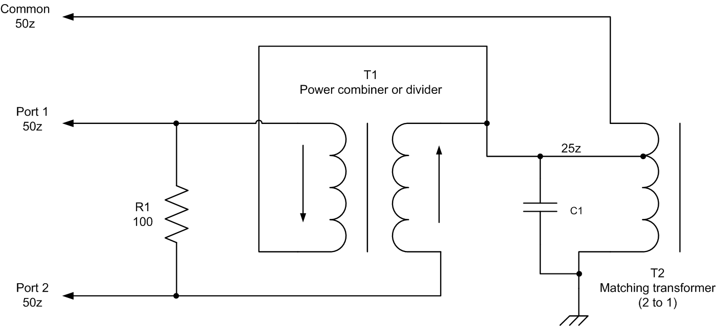
Antenna circuit diagramAntenna coupler motorized A typical isolating power combiner circuit consists of 2 input ports, 1Power antenna relay diagram.
Example diagram of an antenna system with an in-house modulated channelHomebrew antenna tuner Rf splitters/combiners from heros technology ltd[diagram] harada power antenna wiring diagram.

1.8 to 54 mhz combiner set
Software defined radio for mariners: beginner antennasA two and three-antenna combiner electric diagrams (a,b), and the .
.


1.8 to 54 MHz combiner set

RF Venue COMBINE4 4-Channel Antenna Combiner with CP COMB4CPB

antenna circuit diagram - Wiring Diagram and Schematics

RetroSound PA02 Power Antenna Installation Guide

Pelican Parts Forums - Antenna wiring - question for electrical guru's

Example diagram of an antenna system with an In-House modulated channel